“Turtle” the Robot
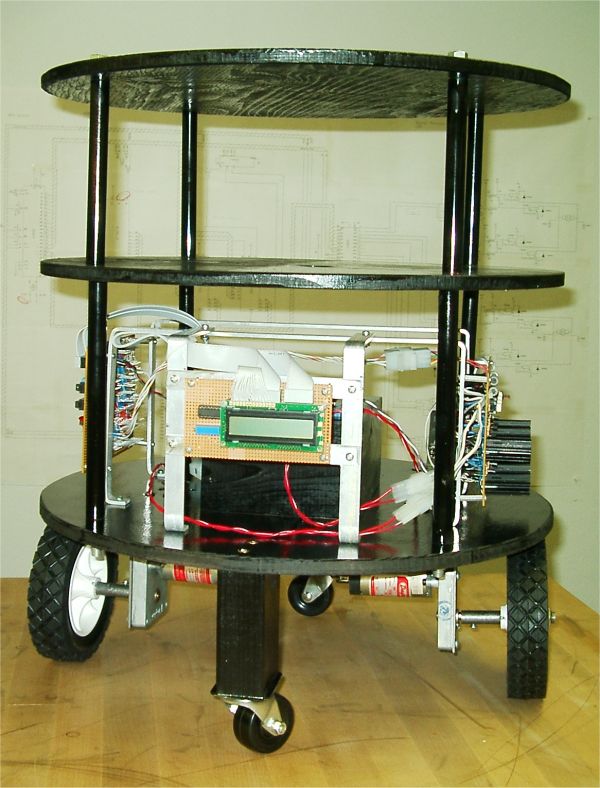
“Turtle” is the name given to this project; a friend of mine actually came up with the name. I was describing how the “motor deck” was going to have its own CPU and would recieve commands from the “control deck.” The commands would be something like “forward three feet”, “rotate left 90 degrees”, ect… He responsed “Oh, like the old turtle logo programing language.” The name stuck.
I’ve started planning for the “control deck” and “sensor deck”. The “motor deck” uses a motorola 6808 8-bit processor. It will take commands from the “control deck” and return data from the line follower and shaft encoders. By breaking the robot into separate decks with multiple processors I get to off load service routines from the main processor on the “control deck”. The “control deck” will have a single motorola 68010 processor. A serial port on the “control deck” will allow me to download and upload data to a PC or handheld device. The “sensor deck” will have a 6808 that processes commands from the controll deck and returns data from various sonar and IR senors. I’m planning on placing three sonar units on servos. A second 6808 on the “sensor deck” will probably be used to handel the PWM to the servos.
In the photo above the empty “control deck,” middle level, and “senor deck,” top level, are present. I’ll put detailed plans, schematics and source code on my web site as the project progresses.
Pictures, Circuit Schematics and data sheets are also available from this site.
Project Log:
11/30/2002
My robot project is progressing very well. The motor deck is about 80% complete mechanically and about 50% complete software wise. The CPU, H-Bridge and display are complete. The chassis is also complete. I still need to add hardware for shaft encoders and a line follower. The command interface sofware is complete and functioning, as is the PWM software that will control the H-bridges. Examples of the software are available from this site.
01/01/2004
After a very long break I have started working on this project again. Part of the reason I took such a long break is that I was stuck tring to get the shaft encoders to work the way I wanted. I was never able to find a ready made solution. I ended up purchaseing some machine shop equipment and made my own shaft encoder hardware.
The shaft encoders use quaditure encoding to sense direction. Normally the two wave forms are fed to a CPU and software is used to determine direction. I decided that it would be a better use of CPU cycles to use hardware to decode the direction of rotation. Check out the schematic for the Motor Deck CPU. A pair of NAND gates and three NOR gates translate the phase of the signal coming from the two optos into two inputs for the CPU. One input pulses when the wheel rotates clockwise and the other input pluses when the wheel rotates counter-clockwise. This form of input requires fewer CPU cycles to deal with in the software.
Check out the new photos on this project, also check out the “Machine Shop” section added to the main site.
Resources
| Name | Link |
|---|---|
| Schematic Page 1 | 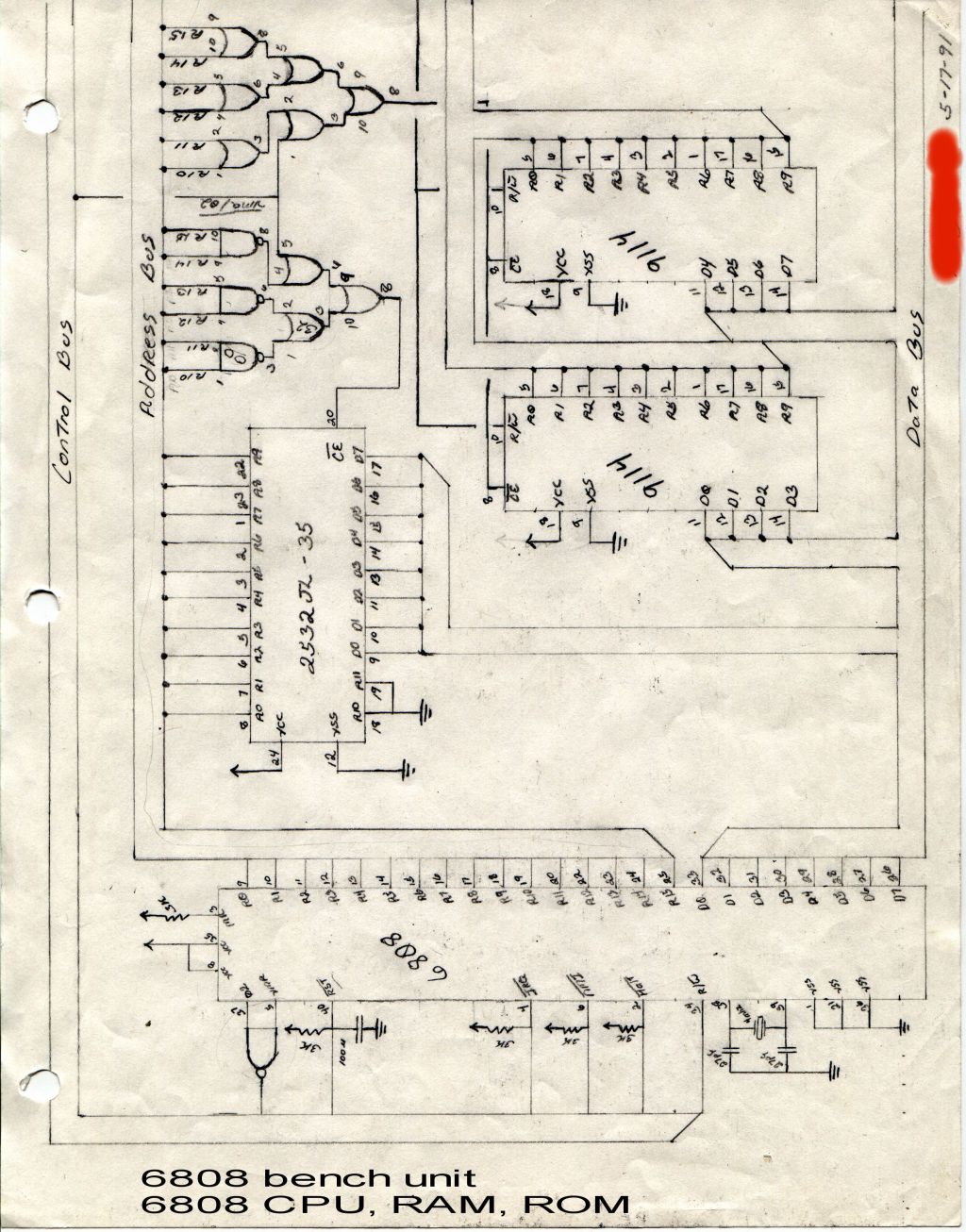 |
| Schematic Page 2 |  |
| Schematic Page 3 |  |
| Cross Compiler | |
| Cross Compiler Manual | |
| Memory Map | |
| ROM Routines |